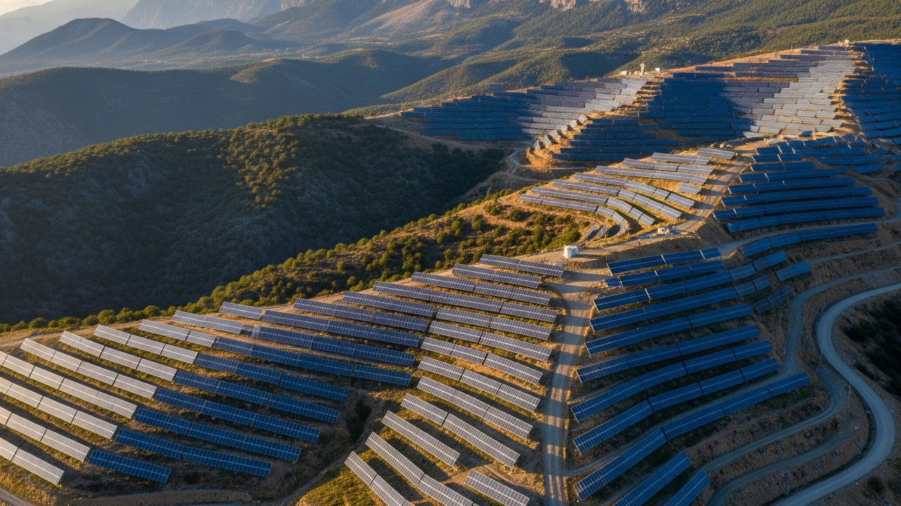
Solar projects on mountainous, sloped terrain can become costly and time-consuming with traditional approaches. On the Antalya-Korkuteli project, data-driven strategic interventions with PVGround delivered significant gains in both cost and installed capacity.
Étape 1
Creating and Analyzing the Digital Terrain Model
Workflow: High-resolution topographic maps are first built from drone or satellite data to understand site conditions. This produces a three-dimensional (3D) digital model of the terrain.
Antalya scenario: The digital model of the Korkuteli site shows clear elevation differences between west-facing slopes and shallower valleys. The model reveals slopes exceeding 25% in the northern section, making construction particularly challenging.
Terrain topography generated with PVGround
MP4Étape 2
Defining Construction Boundaries and Constraints
Workflow: In advanced grading software (PVGround), construction boundaries are defined so arrays can be placed within the desired slope range.
Antalya scenario: When defining the project area, steep terrain and unsuitable earthwork conditions pushed us toward alternative engineering approaches. PVGround enabled extensive production analysis alternatives, supporting a stronger pre-feasibility study.
Investors often want the entire site filled; as engineers, we need to consider critical points before grading everything:
- Which rack type fits the slope: long racks or short racks?
First PVsyst simulation: 2×28 rack
How a 2×28 rack behaves across a zone with three different slopes at once:
PVGround layout: 2x28 rack
MP4Same zone with 2×14 rack type
Next, the same zone with a 2×14 rack type:
PVGround layout: 2x14 rack
MP4Shading difference
Short racks adapted better to the terrain surface, producing a 1.5% difference in shading. On steep slopes, short racks appear to be the better choice.
Étape 3
Automatic Grading and Earthwork Optimization
Workflow: PVGround analyzes thousands of grading scenarios within defined boundaries and constraints in seconds. The goal is to balance cut and fill volumes ("zero net earthworks" target).
Antalya scenario: Because northern, southern, and western slopes are steep, we applied targeted collision-prevention cuts to compare earthwork and production impact.
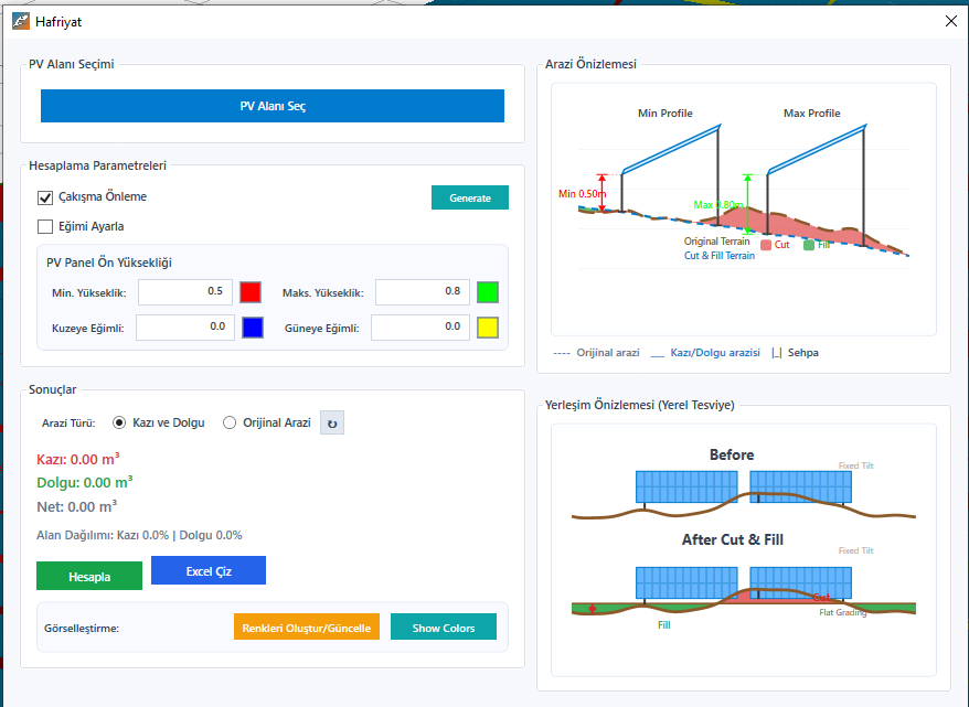
PVGround Earthworks button: frame front height min/max
PVGround earthwork analysis for collision prevention
MP4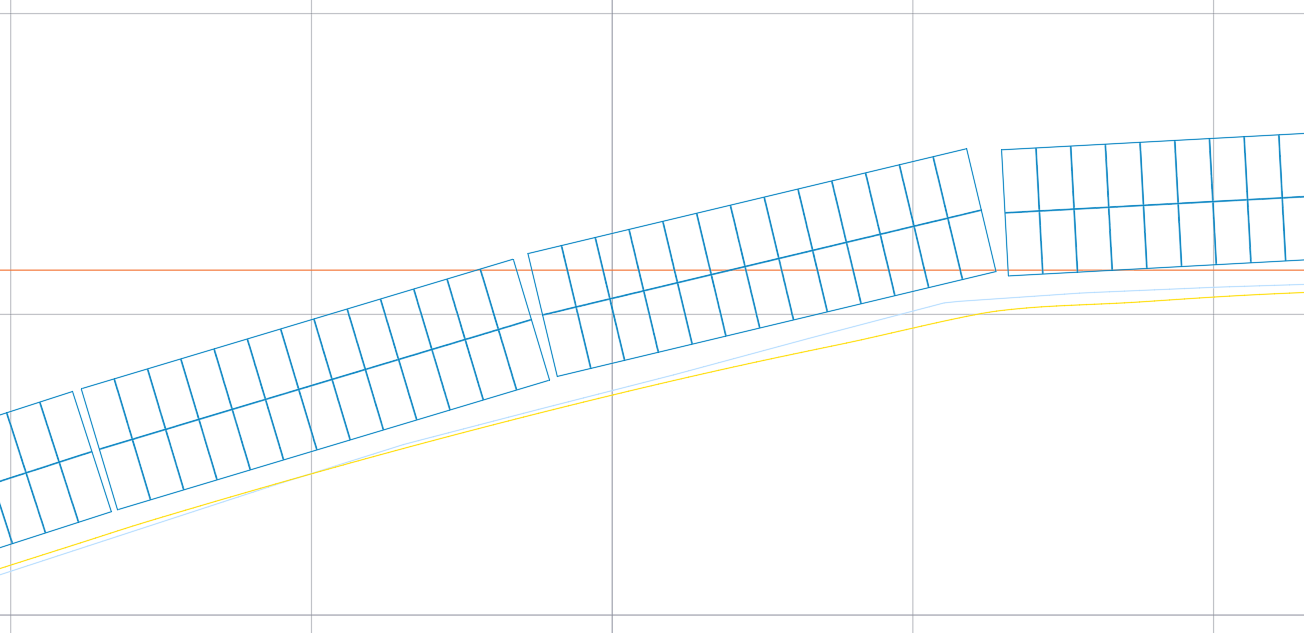
Original vs. new elevation comparison
20.99 m³
Targeted cut volume
14.28 kWp
Recovered power (single rack)
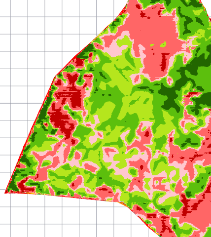
Cut-fill map after optimization
Étape 4
Integrated Panel Layout and Final Design
Workflow: Panel layout is placed on the optimized terrain model. The software checks pile depths and whether the final terrain is suitable for installation.
Antalya scenario: Layout follows the newly graded terrain. The system confirms slopes are installable and all rows remain within slope tolerances and collision-free zones: improving constructability and structural life.
Conclusion: The Power of Strategic Optimization
This project proves that data-driven, targeted interventions can outperform large-scale, costly grading.
Starting point: recover a single 14.28 kWp rack with only 20.99 m³ of cut. Scaled across 300 racks, just 7,598 m³ of earthworks brought back 4,284 kWp (4.28 MWp) that would otherwise have been lost.
This approach replaced a traditional full-site blind grading plan that would have required roughly 26,930 m³ of earthworks.
The Difference: Engineering Choice
The 19,332 m³ earthwork gap between the two approaches was a strategic decision with clear site impact:
- Major cost savings: dozens fewer truckloads minimized earthwork costs.
- Faster schedule: targeted work significantly accelerated construction.
- Lower environmental impact: minimal terrain disturbance improved sustainability.
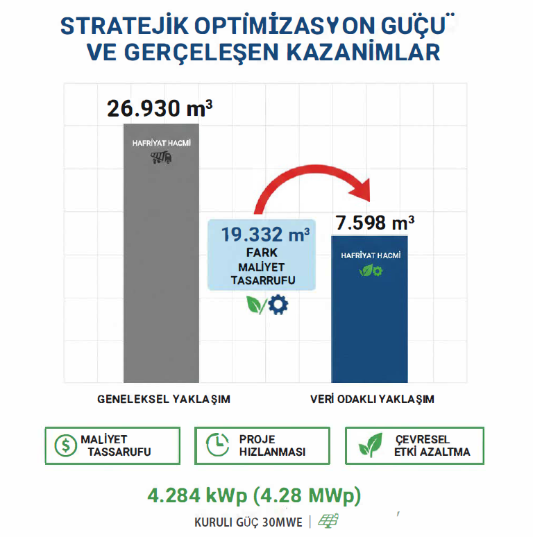
Project optimization results summary
The Antalya-Korkuteli project disproves the idea that "more cut always means better." With PVGround, less intervention delivered higher value: reducing cost while increasing total project yield and investment efficiency.